
A Piping and Instrumentation Diagram (P&ID) is a technical drawing that illustrates the relationship between process equipment and the piping system.
Unlike a simple layout drawing, a P&ID focuses on how a process functions rather than where equipment is physically located.
A typical P&ID includes:
- Pipes
- Pumps
- Valves
- Tanks
- Heat exchangers
- Compressors
- Sensors
- Instruments
- Control loops
- Process flow direction
The goal is to provide a complete picture of how fluids move through an industrial system and how that system is monitored and controlled. If you’re new to industrial engineering, understanding what is instrumentation provides helpful background before learning how to read P&IDs.
P and ID Meaning
Many people search for p and id meaning, which is simply another way of writing P&ID.
The abbreviation stands for:
- P = Piping
- & = And
- ID = Instrumentation Diagram
Together, these words describe a drawing that combines piping layouts with the instruments used to monitor and control industrial processes.
Although different industries may use slightly different drafting standards, the overall purpose remains the same.
Why Are P&IDs Important?
P&IDs serve as one of the most valuable documents throughout the life of an industrial facility.
They help teams:
- Understand system operation
- Plan maintenance
- Perform troubleshooting
- Improve plant safety
- Train new employees
- Support equipment upgrades
- Prepare operating procedures
- Verify engineering designs
Without accurate P&IDs, maintenance work becomes slower and the risk of errors increases.
What Information Does a P&ID Show?
A P&ID contains much more information than a basic process sketch.
Process Equipment
Major equipment may include:
- Storage tanks
- Pumps
- Mixers
- Boilers
- Cooling towers
- Reactors
- Compressors
Each piece of equipment receives a unique identification number.
Piping
Pipes connect equipment throughout the system.
A P&ID often identifies:
- Pipe size
- Material
- Flow direction
- Line numbers
- Service type
Valves
Valves control how liquids or gases move through the system.
Examples include:
- Gate valves
- Ball valves
- Globe valves
- Check valves
- Pressure relief valves
- Control valves
Each valve has its own standardized symbol.
Instrumentation
Instrumentation monitors process conditions.
Common instruments measure:
- Pressure
- Temperature
- Flow rate
- Liquid level
- Density
- Speed
Many facilities also use what is telemetry systems to transmit this operational data to centralized monitoring stations in real time.
These devices help operators keep the process running safely.
P & ID Meaning in Engineering
The phrase p & id meaning is commonly used by students and professionals searching for engineering information.
Within engineering, P&IDs provide a shared language between different teams.
Mechanical engineers use them to understand piping systems.
Electrical engineers reference them for instrumentation.
Process engineers rely on them to optimize production.
Maintenance technicians use them during repairs.
Because everyone reads the same diagrams, communication becomes faster and more accurate.
P&ID Meaning in Engineering
When discussing p&id meaning in engineering, the diagram represents far more than a drawing.
It becomes the primary reference document used during:
- Plant design
- Equipment installation
- Commissioning
- Daily operation
- Preventive maintenance
- Emergency response
- Facility expansion
Engineers update P&IDs whenever system modifications occur to keep documentation accurate.
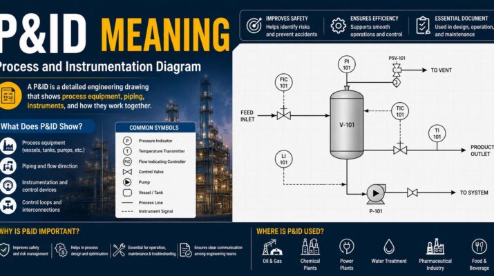
Common Symbols Found on P&IDs
P&IDs use standardized symbols instead of detailed pictures.
Although standards vary slightly, you’ll commonly find symbols representing:
| Symbol Category | Purpose |
|---|---|
| Pumps | Move liquids through the system |
| Valves | Control or stop flow |
| Tanks | Store materials |
| Compressors | Increase gas pressure |
| Heat Exchangers | Transfer heat |
| Flow Meters | Measure flow rate |
| Pressure Gauges | Monitor pressure |
| Temperature Sensors | Measure temperature |
| Control Valves | Automatically regulate process conditions |
Learning these symbols is one of the first steps in reading engineering drawings. Since flow measurement is a key part of many industrial systems, understanding what is a weir can provide additional insight into how engineers measure and control flowing water.
How to Read a P&ID
Reading a P&ID becomes much easier when approached step by step.
Step 1: Review the Title Block
The title block usually contains:
- Drawing number
- Revision number
- Project name
- Approval information
Step 2: Locate Major Equipment
Identify the largest components first.
This helps you understand the overall process before examining smaller details.
Step 3: Follow Process Flow
Most diagrams include arrows showing how fluids move through the system.
Following these arrows helps you understand the process sequence.
Step 4: Identify Valves
Notice where valves control, isolate, or redirect flow.
These components are often key to maintenance and troubleshooting.
Step 5: Review Instrumentation
Examine sensors and control devices.
Many instruments connect to automated systems that use components such as what is an actuator to regulate pressure, temperature, and flow while keeping industrial operations running efficiently.
Industries That Use P&IDs
Piping and Instrumentation Diagrams are used in many industries.
Common examples include:
- Oil and gas
- Chemical manufacturing
- Water treatment
- Food processing
- Pharmaceutical production
- Power generation
- Mining
- Paper manufacturing
- Beverage production
Any facility involving complex process systems is likely to use P&IDs. Many of these industries also maintain a single source of truth so equipment data, operational records, and process information remain consistent across monitoring and maintenance teams.
Benefits of Using P&IDs
Organizations rely on P&IDs because they improve both safety and efficiency.
Better Communication
Everyone works from the same engineering documentation.
Improved Safety
Operators can identify shutdown valves, emergency systems, and safety equipment quickly.
Easier Maintenance
Technicians can locate components faster.
Simplified Training
New employees learn system operation more effectively with detailed diagrams.
More Accurate Planning
Engineers use P&IDs when designing upgrades or expanding facilities.
Common Mistakes Beginners Make
Learning to read P&IDs takes practice.
These mistakes are common among new students.
Confusing P&IDs With Process Flow Diagrams
A Process Flow Diagram (PFD) provides a high-level overview.
A P&ID contains much greater technical detail.
Ignoring the Legend
Every drawing includes symbols and abbreviations.
Reviewing the legend prevents misinterpretation.
Overlooking Revision Numbers
Using outdated drawings can lead to incorrect maintenance decisions.
Always confirm the latest revision.
Assuming Equipment Locations
P&IDs show process relationships, not exact physical locations.
Facility layout drawings provide physical positioning.
Quick Comparison: PFD vs P&ID
| Feature | Process Flow Diagram (PFD) | Piping & Instrumentation Diagram (P&ID) |
|---|---|---|
| Detail Level | General | Highly detailed |
| Equipment | Major equipment only | Complete equipment listing |
| Instrumentation | Limited | Extensive |
| Control Systems | Basic | Full control loops |
| Maintenance Use | Limited | Frequently used |
| Construction Reference | General | Detailed engineering reference |
Tips for Students Learning P&IDs
If you’re studying engineering or industrial technology, these habits can speed up learning.
- Learn standard engineering symbols first.
- Practice following process flow lines.
- Study one system at a time.
- Compare PFDs and P&IDs to understand the differences.
- Review real industrial examples whenever possible.
- Ask instructors about instrument tag numbers and control loops.
With regular practice, reading P&IDs becomes much easier.
Frequently Asked Questions
What does P&ID stand for?
P&ID stands for Piping and Instrumentation Diagram, a detailed engineering drawing used to represent industrial process systems.
What is p&id meaning engineering?
P&id meaning engineering refers to the engineering document that shows piping, equipment, instrumentation, and process control systems within an industrial facility.
What is the difference between a PFD and a P&ID?
A Process Flow Diagram provides a simplified overview of a process, while a P&ID contains detailed information about equipment, valves, piping, and instrumentation.
Who uses P&IDs?
Engineers, operators, maintenance technicians, construction teams, project managers, and safety professionals all use P&IDs during the design and operation of industrial facilities.
Are P&IDs used after construction?
Yes. They remain essential throughout the life of a facility for maintenance, troubleshooting, inspections, upgrades, and employee training.
Key Takeaways
Understanding P&ID meaning is an essential skill for anyone studying or working in engineering, manufacturing, or industrial operations. These diagrams provide a detailed view of how equipment, piping, and instrumentation work together to keep complex systems operating safely and efficiently.
Whether you’re a student learning engineering fundamentals or a professional beginning your career, becoming comfortable with P&IDs will make it easier to interpret industrial processes, communicate with technical teams, and solve real-world operational problems.